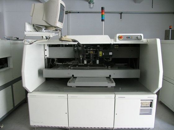
UNIVERSAL 6360E SMTpart
Specifications
- Origin
- china
- Price Term
- EX-Work
- Payment Term
- T/T
UNIVERSAL 6360E SMTpart is a Electronics Production Machinery product. Key specs — Origin: china; Price Term: EX-Work; Payment Term: T/T.
Product Description
All resistor verifications are programmed the same way. The ERV automatically selects the verification method depending on the value entered in the Value data field.
. Example: Mid-range resistor at 1000 ohms, plus or minus 10%. Value = 1000s, Tolerance = 10
Resistors verified between 900 and 1100 ohms pass.
Opens Verification
Use the opens verification to verify components having 10 megohms and greater resistance. This verification can also be used to verify that there is no component in the verifier contacts.
Range: 10 megohms and greater.
Tolerance: Any value of 10 or less in the tolerance data field defaults to 10% tolerance. Any value greater than 10 is accepted as programmed.
Details: The ERV tests an internal 1 megohm resistor in parallel with the verifier contacts, at plus or minus 10%. Thus, any component of 10 megohms or greater passes.
Shorts Verification
Use the shorts verification to verify electrical continuity for jumper wires or small inductors or to verify the verifier contacts for a maximum resistance of 10 ohms.
Range: 10 ohms and less.
Tolerance: Any value of 10 or less in the tolerance data field defaults to 10% tolerance. Any value greater than 10 is accepted as programmed.
Details: The ERV tests an internal 100 ohm resistor in series with the verifier leads, at plus or minus 10%. Thus any component of 10 ohms or less will pass.
Example: This step is a typical shorts verification for 10 ohms or less.
Comments: None.
This verification is for convenience only and should be used sparingly. Because it uses relatively high currents (100 milliamps), excessive use could shorten the expected life of the test relays.
Diode Voltage Verification
Use the diode verification to ensure that diodes are oriented correctly and their voltage drop is within the specified limits.
Range: 100 millivolts to 9.99 volts. Enter the value using one of the following suffixes.
#NAME? Details: 10 milliamps is recommended for the current applied value.
Example: This verification step is for 750 millivolts, plus or minus 10% at 10 milliamps.
Value = 750m, Tolerance = 10, Current Applied = 10
Comments: If the manufacturers’ data does not include diode voltage drops, use the following typical values for creating diode verifications
Silicon diodes: 0.74 volts, +/- 20%
Germanium diodes: 0.36 volts, +/- 30%
Schottkey diodes: 0.45 volts, +/- 25%
LEDs: 1.3 to 2.2 depending on composition (refer to the data
sheets) -High voltage rectifier diodes may be two or more silicon diodes in series. Select the voltage accordingly.
Zener Voltage Verification
Use the zener verification to verify zener diodes to ensure that they are of the required voltage value and that they are oriented correctly.
Range: 100 millivolts to 50 volts. Enter the value using one of the following suffixes.
#NAME?
#NAME? Details: The test currents for zener diode verifications are entered in discrete values as follows: 1, 2, 5, 10, 20 and 50 milliamps (10 milliamps is recommended).
Example: This verification is for 5.1 volts, plus or minus 10% at 10 milliamps.
Value = 5.1s, Tolerance = 10, Current Applied = 10
Comments: Most zener diodes, if verified in reverse, verify as normal silicon diodes.
Some precision-voltage reference diodes, however, incorporate a normal diode in series. These verify open in reverse.
Capacitance Verification
Use the capacitance verification to verify the value and quality of capacitors.
#NAME?
#NAME?
#NAME?
The ERV employs two different methods for verifying capacitors depending on value.
Capacitors up to 9.99 microfarads are verified in an AC bridge at 1 kHz. Dissipation factor limits may be specified. Polarity may also be specified.
Capacitors above 10 microfarads are verified by measuring the charging current resulting from a uniformly increasing applied voltage ramp. A positive ramp is applied unless a negative polarity is specified. No dissipation factor is possible with this ver
A capacitance test alone does not test for polarity (orientation). To verify polarity, a leakage test for that component must be programmed in addition to the capacitance test. The leakage test must be performed before the capacitance test. Refer to the Leakage Verification topic for details.
Performing a leakage test to verify polarity significantly increases verification time.
Because the ERV verifies only to symmetric tolerances, it is necessary to convert components with asymmetric tolerances to a symmetric value and revise the nominal component value.
For example
The range defined by 10 .F, +80% -20% is equivalent to the range defined by 13 .F, +/- 38%.
Note that both the value and tolerance must be adjusted to create an equivalent range. The following equations are used to calculate a new value and symmetric tolerance from a given value and asymmetric tolerance
(actual high limit) + (actual low limit) New capacitance value = 2
(actual high limit) - (New Value)
Symmetric tolerance =
(New Value)
Using the example 10 .F, +80% -20%
actual high limit = [10 + (10 x .80)] = 18
actual low limit = [10 - (10 x .20)] = 8
(18 + 8)
New capacitance value = = 13
18 -13
Symmetric tolerance = x 100 = 38%
Enter the New Capacitance Value in the Value field.
The Symmetric Tolerance is the value entered in the Tolerance field.
The Dissipation Factor field is optional. It can be used to enter a dissipation factor for capacitors up to 9.99 microfarads. The dissipation factor is entered in tenths of a percent. Dissipation factors can range from 0.1 to 25.4 percent (1 to 254). The dissipation factor is frequency dependent - ensure that the value entered is for 1 kHz. If a dissipation factor is entered, the ERV verifies the actual dissipation of the capacitor and compares it to the number in the Dissipation Factor field. If the actual dissipation exceeds the programmed dissipation factor, the component is failed.
If zero is entered in the Dissipation Factor field, the component dissipation factor is verified if the capacitance is less than 10 .F, but the results are ignored. However, if the results are beyond 25.4 percent, the component is failed with a tolerance failure indication.
Value = .1u, Tolerance = 10, Dissipation Factor = 5
Capacitors with value 10 .F or larger with a working voltage of less than 15 vDC should not be verified.
Current Diode Verification
Use the current diode verification to ensure that current diodes control current to the specified value and that they are oriented correctly.
Range: 100 microamps to 99.9 milliamps. Enter the value using one of the following suffixes.
#NAME?
#NAME? Details: Verification is performed by applying a fixed 10 volts across the component.
Example: Verification is for a 1 milliamp diode with a tolerance of 10%.
Comments: None
Value = 1m, Tolerance = 10
Leakage Verification
Use the leakage verification to verify the orientation of electrolytic (polarized) capacitors, check the reverse leakage of diodes, and check the sharpness of zener diode knees.
The displayed result of a leakage verification is not an error percentage, but rather the actual leakage current.